Rocker Design — SR4: Aurora
(2024–2025)Georgia Tech Solar Racing
Designed and integrated rocker arms to enable suspension adjustability between comfort and handling — optimizing performance in track and endurance races for the team's first multi-occupant vehicle.
Skills & Software
Introduction
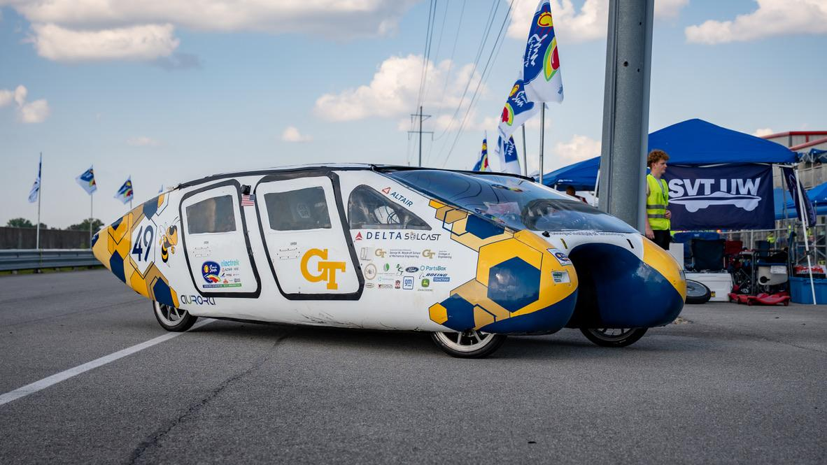
This project covered the design, validation, and integration of the rocker component for a double A-arm front suspension on SR4: Aurora, a multi-occupant solar vehicle developed by Georgia Tech Solar Racing. As the second-iteration suspension design, this project enabled the vehicle's transition from a vertical to a horizontal suspension architecture.
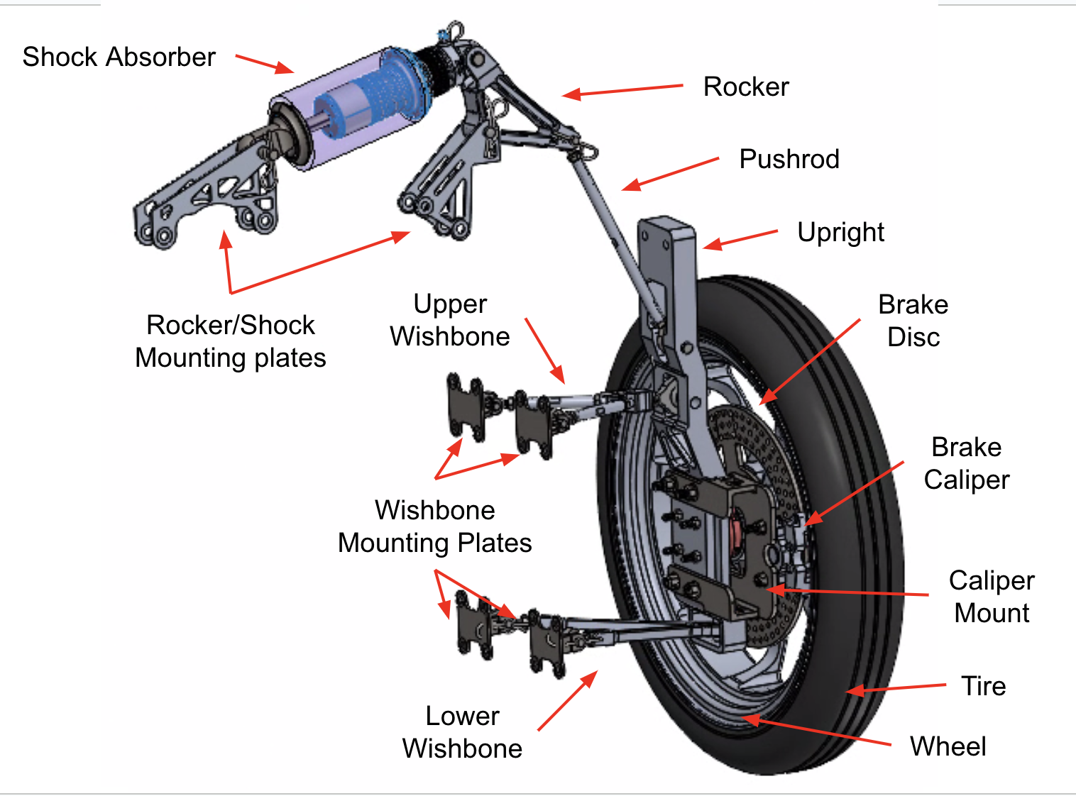
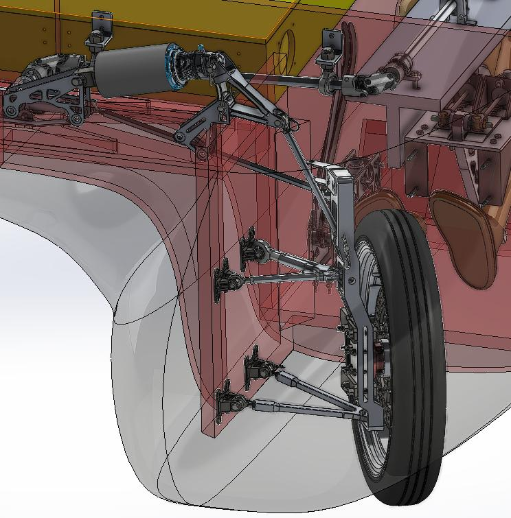
The rocker transfers vertical wheel loads into horizontal shock motion: the shock pins directly to the rocker, while the rocker hinge is pinned between a pair of waterjet-cut Al 7075-T6 mounting plates bolted to the composite chassis. A pushrod — machined from Al 2024-T3 tubing — connects the upright to the rocker, completing the load path from wheel to shock.
The component was designed and validated to withstand combined 1-2-1g turn-bump-brake loading scenarios for a 940 kg vehicle, achieving a factor of safety greater than 1.25 relative to material yield strength.
Timeline
- Design and Validation (August 2024 - December 2024)
- Manufacturing and Assembly (January 2025 - May 2025)
Design Overview
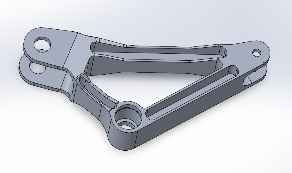
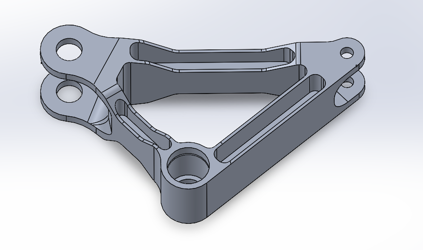
Designed two rocker arms within Solidworks enabling comfort/sport mode adjustability through varying motion ratios, allowing modification of the vehicle's natural frequency and handling characteristics. Under went a lot of design iterations to make the part as light as possible while still maintaining a FoS >1.25.
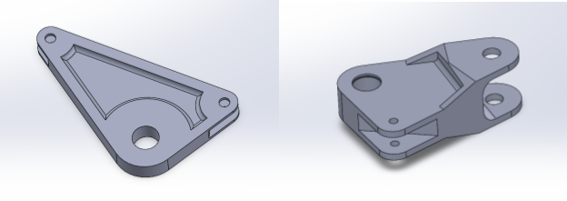
Initial Rocker Designs
Components Involved:
- Inverted Retaining Ring x2
- Inner Race x2
- Drawn Cup Needle Bearing Cage x2
- Dowel Pin x2
- Spacer x2
Hand Calculations
Validated Comfort and Sport rocker variants for bump and sag load cases.
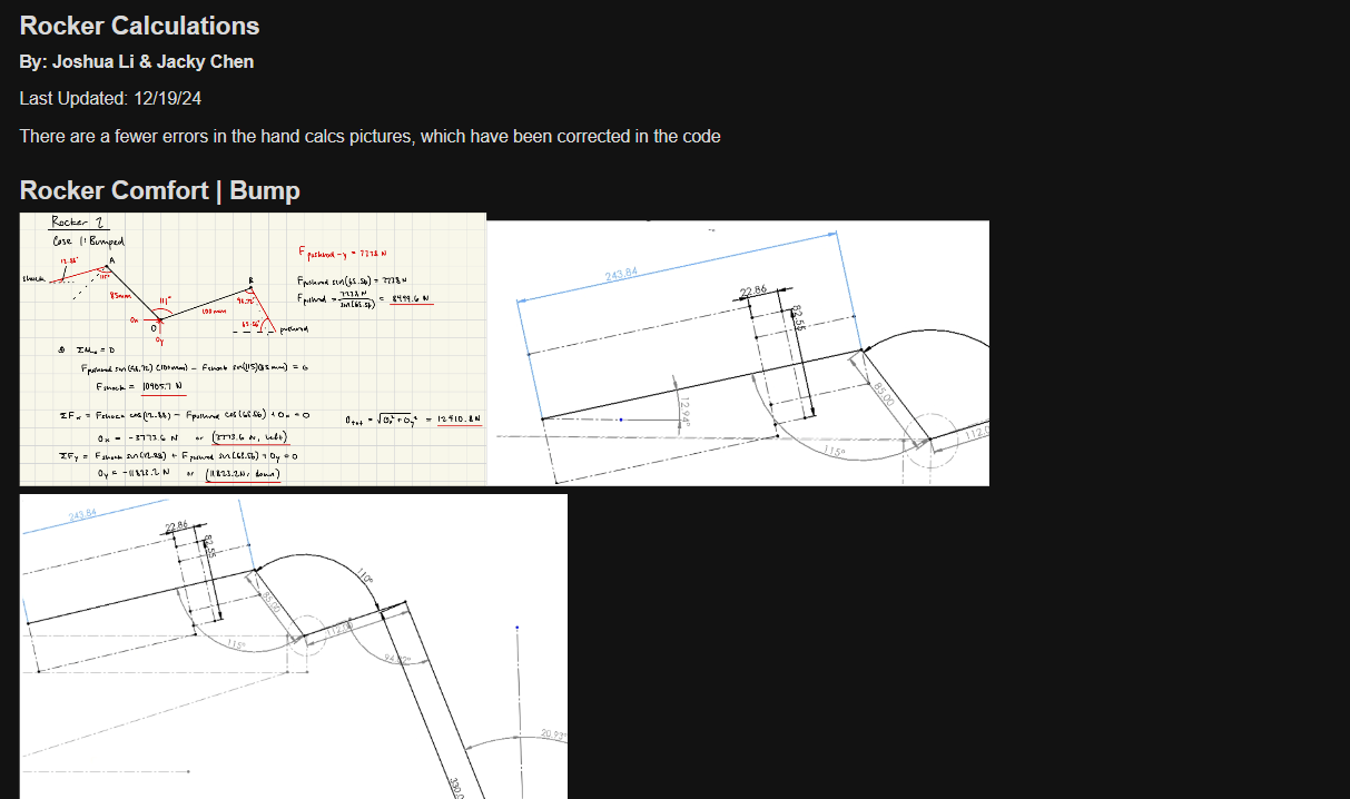
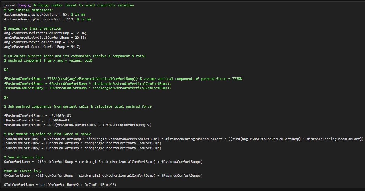
Calculated forces experienced by rocker assuming static equilibrium using worst-case loads (master loads).
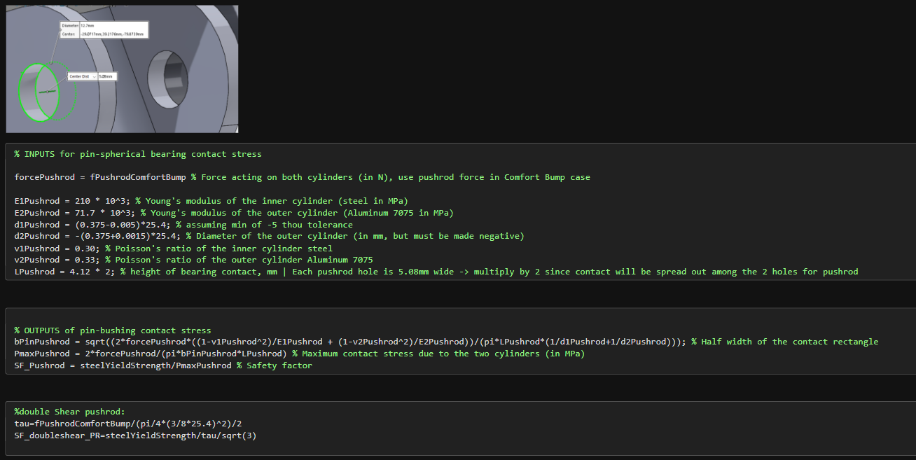
Performed double-shear pin-bearing, contact stress, and radial bearing calculations for the rocker hinge joint.
Rocker FEA
Utilized Ansys Static Structural FEA to validate rocker under 1-2-1g worst case loads.
Material Properties: Uses Al-7075-T6
Mesh: Global Element Size: 1.5mm Comfort Rocker
- Nodes: 98k
- Elements: 48k
- Face Sizing: 0.75mm
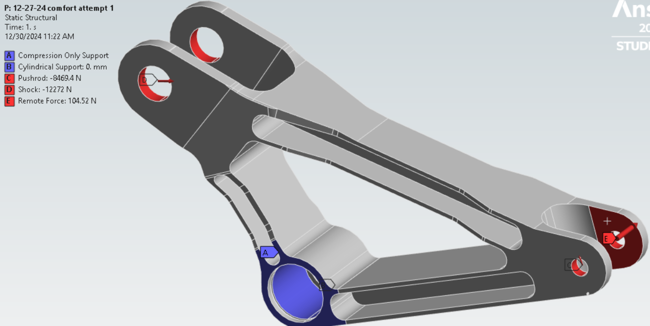
Loads/Constraints:
- Remote force applied to the pushrod
- Shock and pushrod loads applied as bearing-load vectors
- Hinge modeled as a cylindrical support, allowing FEA to automatically solve for the hinge/bearing reaction
- Compression-only supports applied to the hinge's side faces, where it contacts the rocker mount
Comfort Rocker FEA Setup & Results
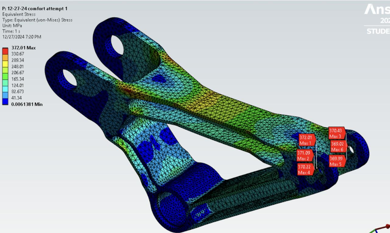
Comfort Bump Max Von-Mises Stress: 372 MPa
Results
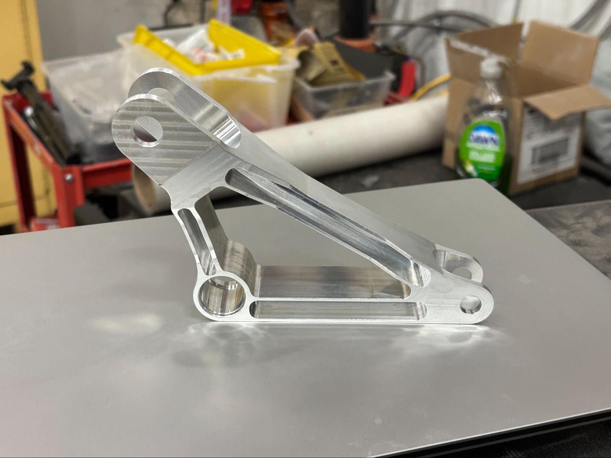
Went from ~450g from initial rocker design to 168g for comfort rocker and 146g for sport rocker after extensive FEA iterations and lightweighting (~60% weight reduction).
All safety factors >1.25 for all hand calculations and FEA simulations.
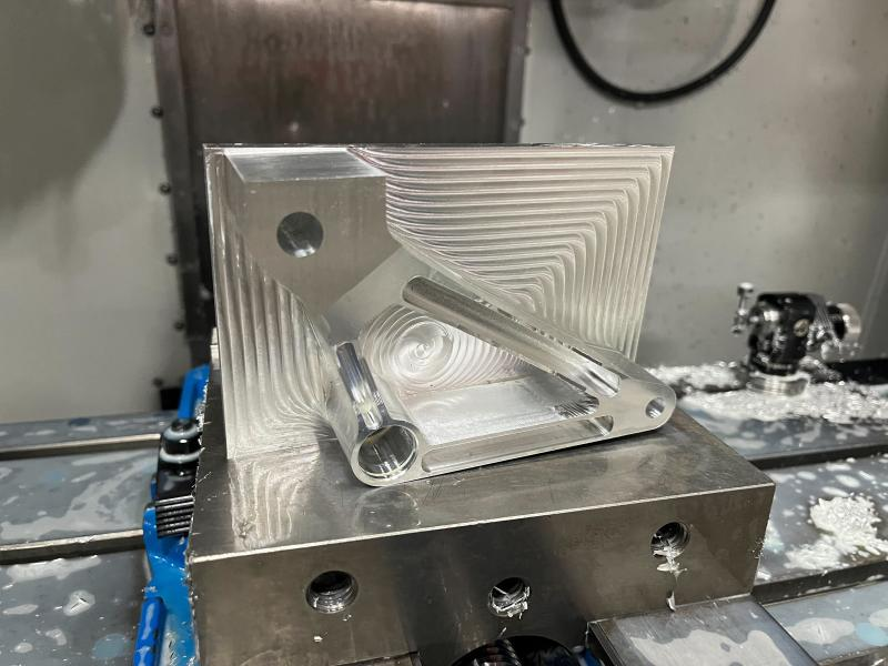
Rocker CAM & Manufacturing
The rocker was CAM'd in Fusion 360 and CNC milled out of Al 7076-T6. The CAM was completed with 2 operations and needed a custom jig to clamp the rocker for OP20.
Conclusion
This whole project was incredibly humbling but rewarding. This was my recruit project entering this team, and I learned so much about the engineering process, taking my part from cradle-to-grave — from concept to design to validation to manufacturing and finally integration. It was great to see the rocker successfully perform at the Formula Sun Grand Prix, where the vehicle placed 3rd in the Multi-Occupant vehicle category.