Front & Rear Suspension — SR-5: Halo
(2025–2026)Georgia Tech Solar Racing
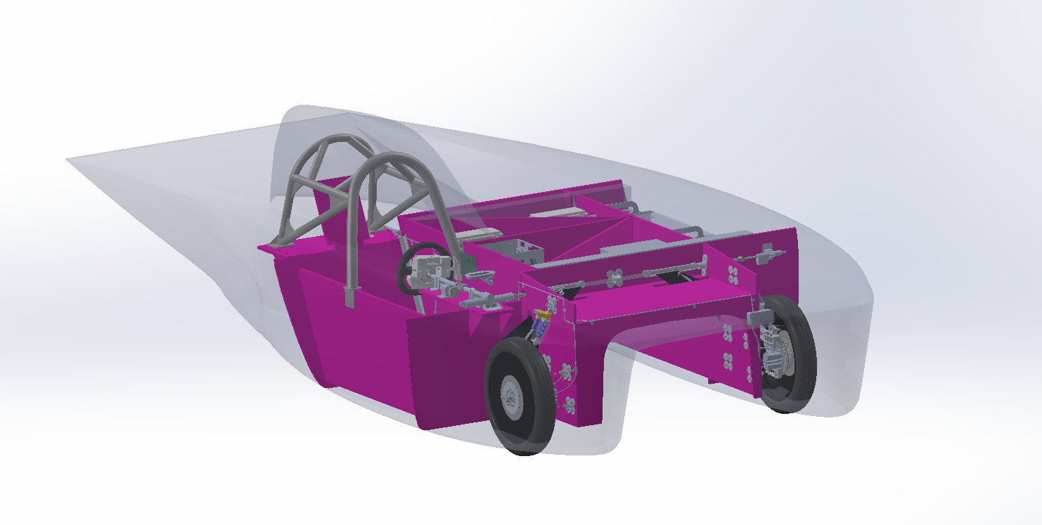
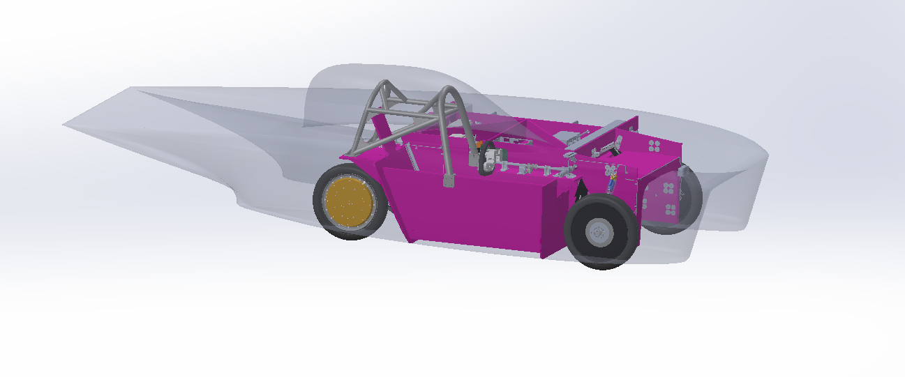
Led the design, validation, and integration of a six-link multilink front suspension system and the rear trailing-arm suspension for the team's newest solar vehicle, SR-5: Halo.
Skills & Software
Introduction
As the suspension subteam lead, I led the design and validation of a six-link multilink front suspension — the first in the team's history — and a trailing-arm rear suspension. This project spanned all the way from conducting trade studies to developing kinematic models to designing and validating every structural component in both assemblies. As subteam lead, I was responsible for high-level design of the suspension and coordinated the team through technical design, validation, and integration challenges to deliver validated and optimized subsystems.
Design Overview
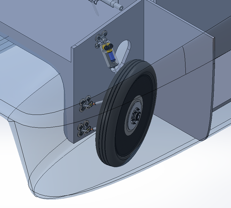
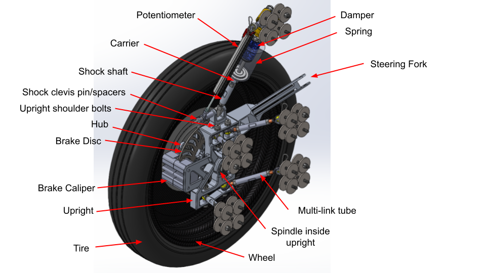
For the front, a trade study weighing leading-arm, double-wishbone, and multilink architectures led to a six-link design: a tie rod, a pushrod/shock, and four links arranged to reproduce double-wishbone-like kinematics. Every link resolves to a two-force member, which simplifies the load-path math, gives extensive tuning adjustability, and packages efficiently — at the cost of requiring careful analysis of load cases unique to the architecture, particularly steering-induced loads and link collapse angles.
For the rear, a trailing arm was carried over conceptually from SR-4 and refined for SR-5's packaging — lighter and narrower than a double wishbone, and it mounts directly to the horizontal chassis panel already planned for the rear, avoiding the extra vertical panel a wishbone would need. This iteration added rod-end adjustability for rear toe and revised arm geometry.
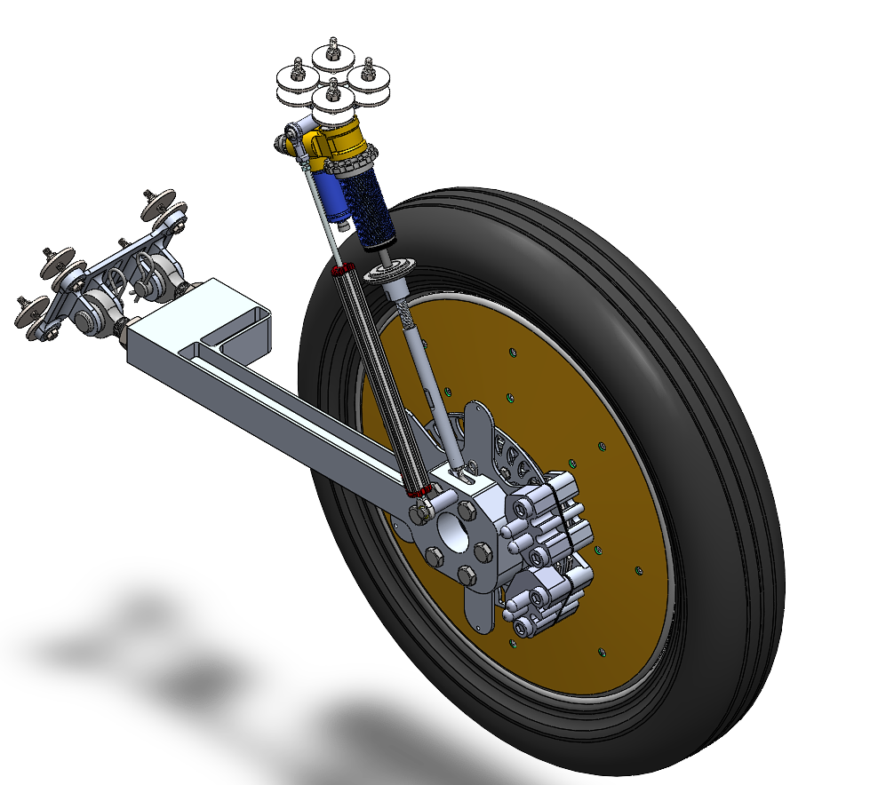
Timeline
- Design and Validation (Fall 2025)
- Rear Suspension CDR (November 2025)
- Front Suspension CDR (December 2025)
- Manufacturing and Assembly (Spring 2026)
Front Suspension
Suspension Kinematics
The parametric kinematic model for the suspension was built in Solidworks to define every suspension pickup point — shock and linkage mounting locations on the upright and chassis — driven entirely by equation-linked parameters. This allows for the tuning of the scrub radius, kingpin inclination, instant centers, roll centers, caster, anti-squat, and anti-dive from the front and side views before a single structural part was modeled.
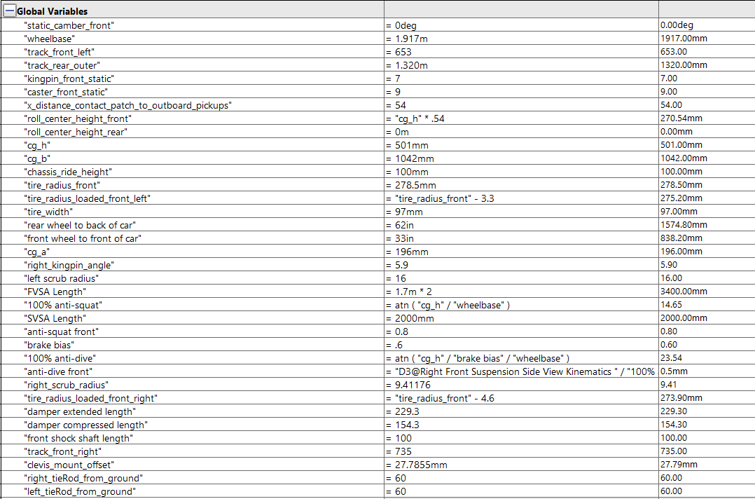
A parametric heave sketch allowed for the whole assembly to be swept through its full range of motion — nominal, full bump, and full sag — so every downstream check (interference, bump steer, loads) could be run at each ride height.
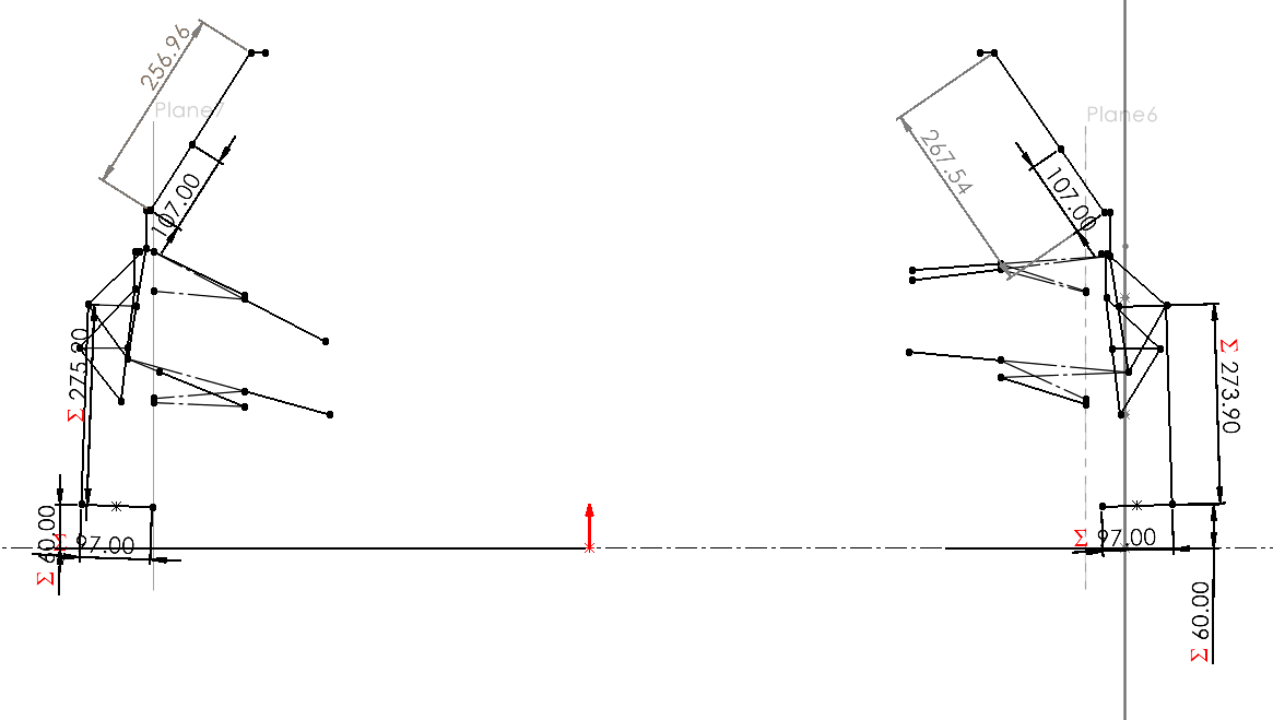
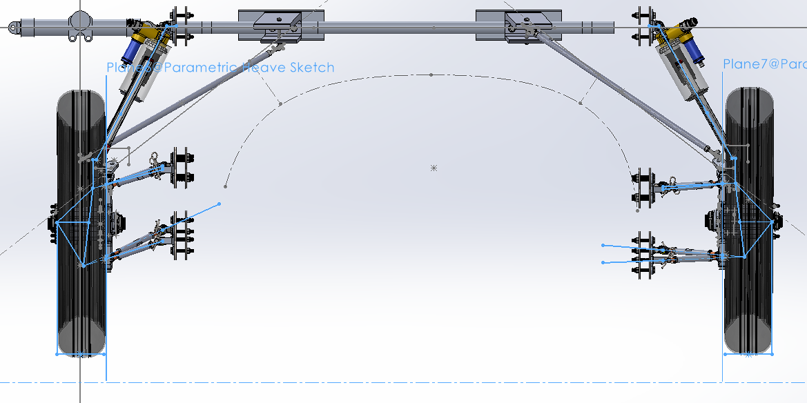
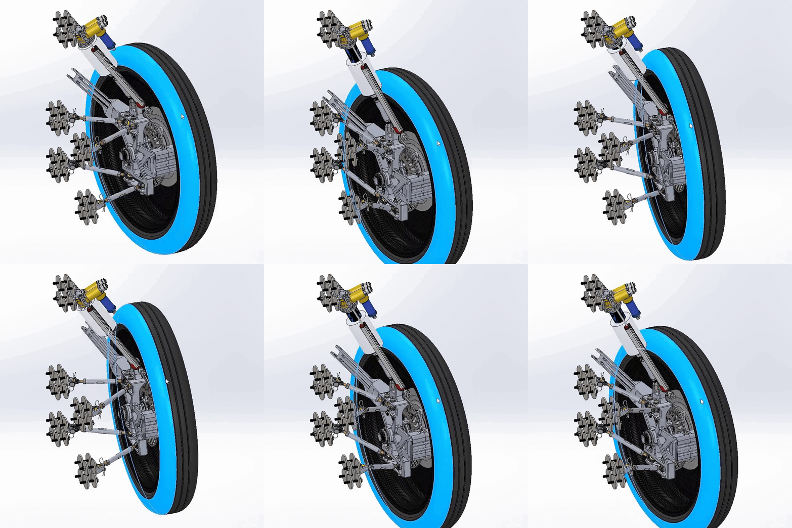
Coilover travel is 75 mm total: 52.5 mm of compression from nominal and 22.5 mm of sag, giving a nominal coilover length of 313.8 mm (261.3 mm at full bump, 336.3 mm at full sag).
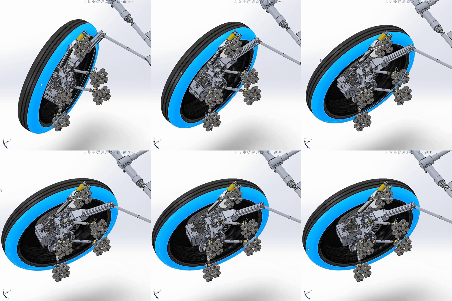
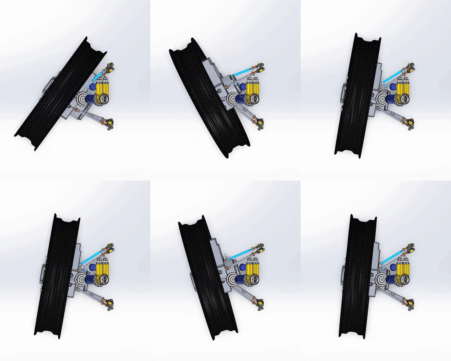
Interference and clearance were checked across every combination of left/right assembly, bump/sag, and left/right steering lock to confirm no contact throughout the full range of suspension travel and steering.
The front suspension assembly comes in at 20.3 kg per corner.
Suspension Dynamics
SR-5's suspension dynamics were critical to controlling handling response, cornering predictability, weight transfer, and traction. Wheel rate, spring rate, and roll stiffness distribution were solved via a MATLAB model targeting a 2 Hz natural frequency, 4°/g roll gradient, and mild understeer characteristics. The full derivation and spring selection process is detailed on the SR-5 simulations project page.
Validation
System-level loads were derived from a master MATLAB loads script that computed worst-case forces for every corner of the car under combined 1-2-1g turn-bump-brake conditions, accounting for the vehicle's front-to-back and left-to-right asymmetry.
These master loads fed directly into component-level statics for every part in the load path.
Most components in the front suspension assembly were validated with both hand calculations and FEA as deemed necessary.
Table 1. Front Suspension Component Validation Summary
| Component | Validation Method | Load Cases | Min Safety Factor |
|---|---|---|---|
| Upright | FEA + hand calcs (bearing stress, bolt shear/bending, pin shear, contact stress) | 4 (L/R turn, w/ and w/o brake) | 1.28 |
| Hub & Spindle | FEA + hand calcs (bearing loads, dowel pin shear, bolt shear, combined bending) | 2 (L/R turn w/ brake) | 1.65 |
| Multi-links | Hand calcs (buckling, axial stress, contact stress) — all 4 link types | Axial tension/compression | 1.30 |
| Coilovers | Hand calcs (thread, stress concentration, buckling, axial) + Instron compression test | N/A | 1.71 |
| Front Clevis Mounts | FEA + hand calcs (bolt shear, pin double shear, bearing stress, finger bending) | 4 (lateral force, tension/compression) | 1.29 |
Rear Suspension
The rear suspension carried the trailing-arm concept forward from SR-4, tuned for SR-5's packaging via a 2D kinematic model targeting maximum shock angle across the full travel range: 69.79° shock angle, 2.77 in total wheel travel (0.83 in sag, 1.94 in bump).
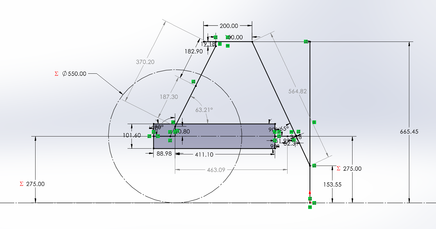
All rear components — trailing arm, coilover, and rear clevis mount, and shock clevis mount — validated against the same master loads model as the front suspension, holding to the 1.25 minimum safety factor standard.
Table 2. Rear Suspension Component Validation Summary
| Component | Validation Method | Load Cases | Min Safety Factor |
|---|---|---|---|
| Trailing Arm | FEA + hand calcs (statics, bending/torsion, pin contact, rod-end) | 2 (L/R turn) | 1.47 |
| Coilover | Same as front suspension coilover | N/A | 1.71 |
| Rear Clevis Mount | FEA + hand calcs (statics, bending/torsion, pin contact, rod-end) | 2 (L/R turn) | 1.47 |
| Shock Clevis Mount | FEA + hand calcs (statics, bending/torsion, pin contact, rod-end) | 2 (Front/Rear) | 2.75 |
Manufacturing and Assembly
After an intense semester of iteration after iteration of design and validation, we arrived at a fully validated front and rear suspension system in the midst of winter break. Following the complete design and validation of the two subsystems, the spring semester marked the start of the manufacturing cycle with hopes to have a fully assembled subsystem by the end of the semester. For each component, I supported development of Manufacturing Quality Review (MQR) documents covering pre- and post-manufacturing procedures — critical tolerances, assembly instructions, manufacturing process and CAM steps where applicable, and post-build validation and testing.
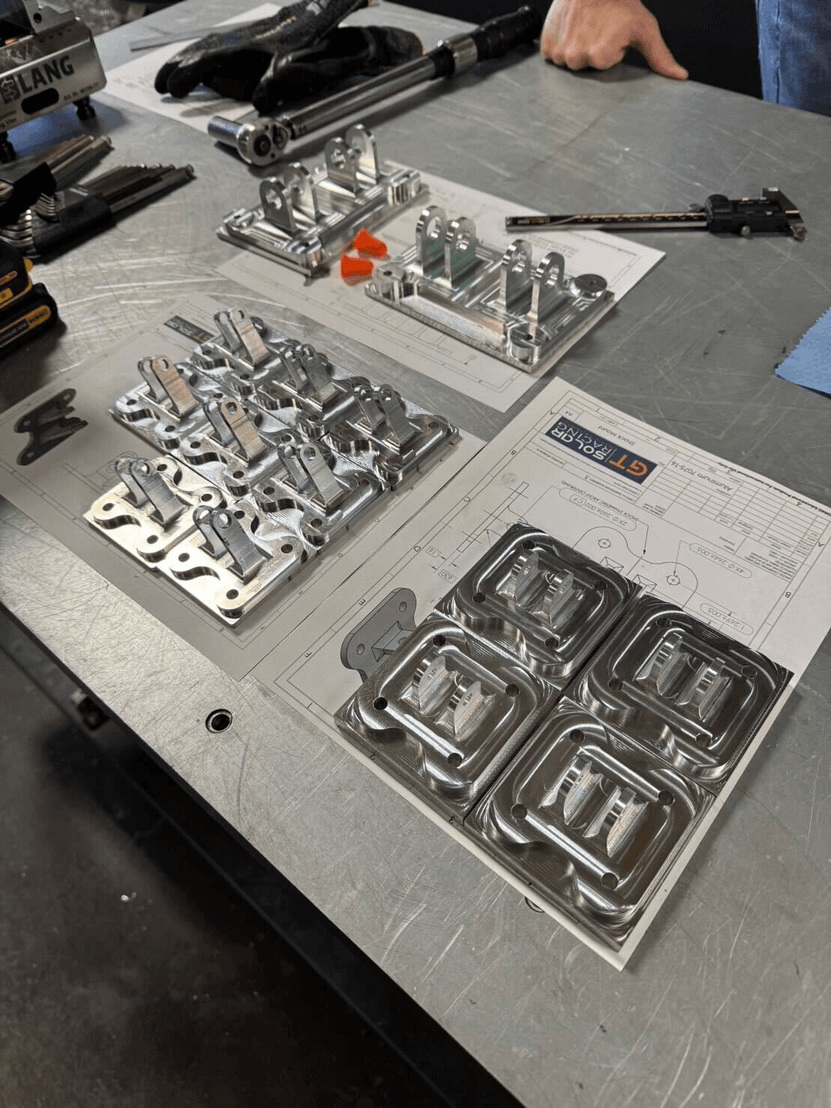
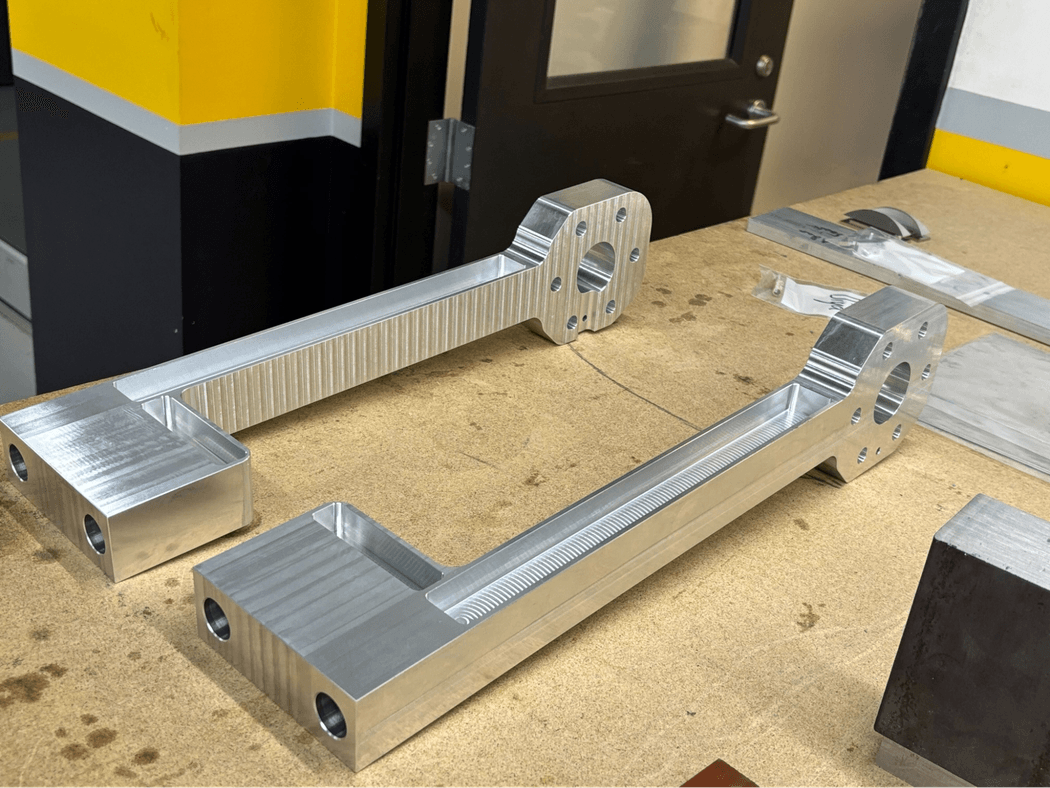
As for manufacturing, most of the suspension components were supported through our gracious sponsor and our school's machine shop (Montgomery Machining Mall). The few components that were manufactured in-house included the multilinks, lots and lots of spacers, and the shock shafts.
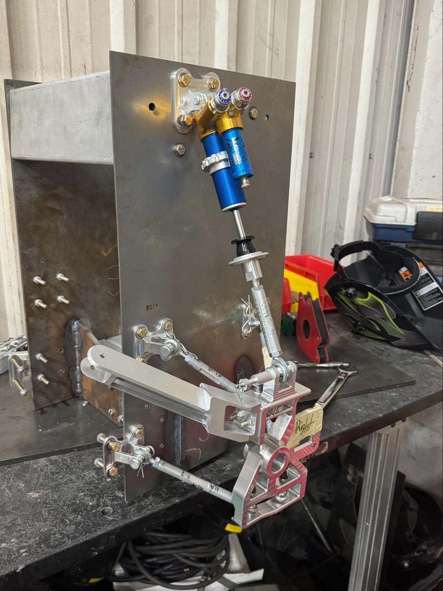
I also designed a simple test rig that allowed for the full assembly of the front suspension to conduct some preliminary tests prior to being mounted on the vehicle. The main motivations were to catch any mechanical interference across its full range of motion. The complete assembly is mounted to the rig plate and cycled through bump, sag, and left/right steering lock — including every combination of those states — with each interference documented and checked against target kinematic quantities.
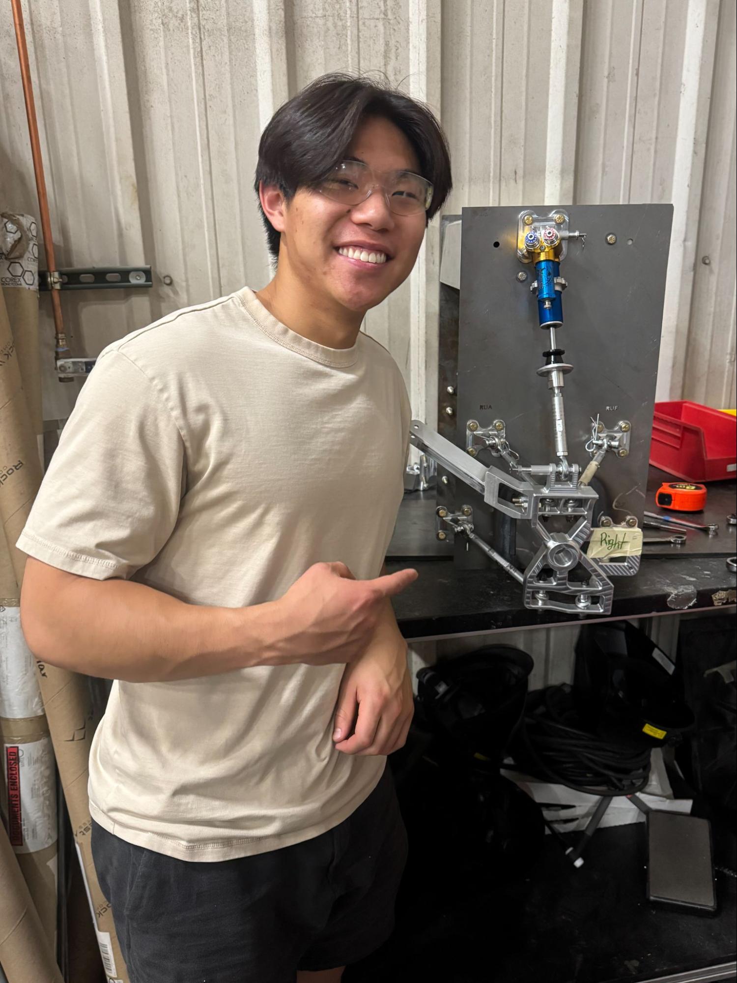
The rig didn't need to be structural, so I used it as a chance to learn TIG welding! The assembled front suspension assembly can be seen below.
Conclusion
Taking these systems from initial concept through fully validated hardware was the most complete design cycle I've run on the team — spanning kinematics and dynamics optimization, component design and FEA guidance, and manufacturing and assembly planning across every part in both suspensions. This was definitely the most demanding project I've led, and the most rewarding. This process has taught me as much about coordinating people as it did about suspension design. As for future steps, we plan to mount this suspension on the vehicle chassis sometime this upcoming Fall semester!